
IPV4
Internet Protocol version 4 is the fourth version of the Internet Protocol. It is one of the core protocols of standards-based internetworking methods in the Internet, and was the first version deployed for production in the ARPANET in 1983. The IPV4 is a highly efficient Internet Protocol, and using a 38-bit naming scheme, IPV4 has a maximum of 4.3 Billion individual addresses.
Internet Protocol is a layer-3 protocol, and it takes data from the Transport Layer and breaks it down into packets. IP packet has the responsibility of encapsulating data unit received from above layer and add to its own header information.
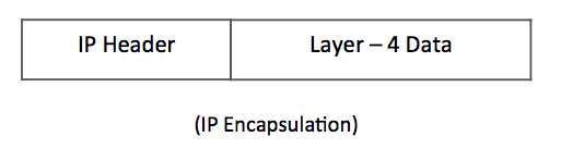
The above is a diagrammatic representation of the process of IP Encapsulation. The first part of the IP address is the header of the respective IP, which is followed by the data that is being taken from the Transport Layer. The encapsulated data as a whole is referred to as the IP Payload. The IP header contains all the relevant information as to where the packet has to be delivered. Some of the details that are stored in the IP Header are as follows:
- Version: Version no. of Internet Protocol used (e.g. IPv4).
- IHL: Internet Header Length; Length of entire IP header.
- DSCP: Differentiated Services Code Point; this is Type of Service.
- ECN: Explicit Congestion Notification; It carries information about the congestion seen in the route.
- Total Length: Length of entire IP Packet (including IP header and IP Payload).
- Time to Live: To avoid looping in the network, every packet is sent with some TTL value set, which tells the network how many routers (hops) this packet can cross. At each hop, its value is decremented by one and when the value reaches zero, the packet is discarded.
- Protocol: Tells the Network layer at the destination host, to which Protocol this packet belongs to, i.e. the next level Protocol. For example protocol number of ICMP is 1, TCP is 6 and UDP is 1
- Time to Live: To avoid looping in the network, every packet is sent with some TTL value set, which tells the network how many routers (hops) this packet can cross. At each hop, its value is decremented by one and when the value reaches zero, the packet is discarded.
- Protocol: Tells the Network layer at the destination host, to which Protocol this packet belongs to, i.e. the next level Protocol.
- Source Address: 32-bit address of the Sender (or source) of the packet.
- Destination Address: 32-bit address of the Receiver (or destination) of the packet.
- Source Address: 32-bit address of the Sender (or source) of the packet.
- Destination Address: 32-bit address of the Receiver (or destination) of the packet
ADDRESSING MODE:
IPV4 supports three types of addressing modes, which we will see in details as follows-
Unicast Addressing Mode:
In this addressing mode, data is sent only to one single destined host. The Destination Address field contains a 32- bit IP address of the destination host. Here the client can send data only to the targeted server.

The above is a diagrammatical representation of the unicast addressing mode.
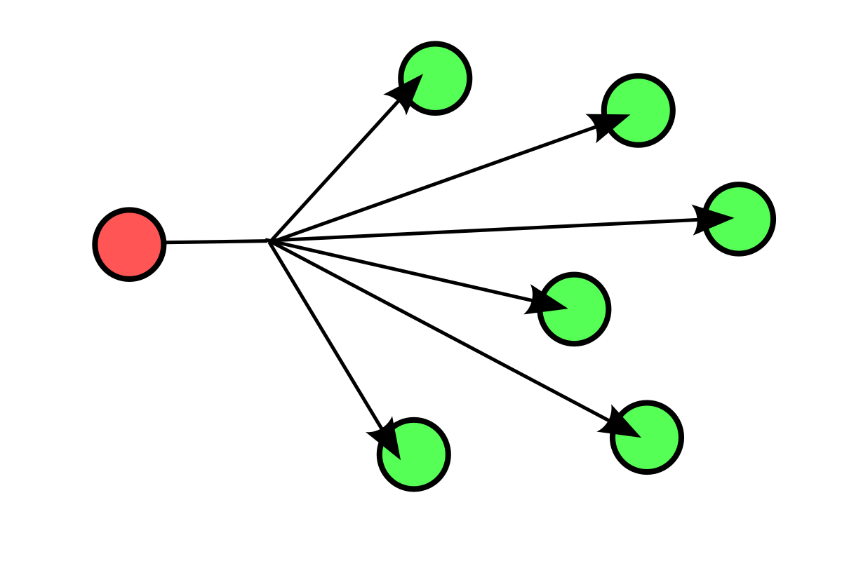
Broadcast Addressing Mode:
In this mode, the packet is addressed to all the hosts in a network segment. The Destination Address field contains a special broadcast address, i.e. 255.255.255.255. When a host sees this packet on the network, it is bound to process it. Here the client sends a packet, which is entertained by all the Servers. We can consider the scenario of broadcast messaging on whatsapp, which is a good real world example to understand this concept.
Multicast Addressing Mode:
This mode is a hybrid versionof the previous two modes. Here, the packet sent is neither destined to a single host nor all the hosts on the segment. In this mode, the Destination Address consists of a special address which starts with 224.x.x.x and can be accessed by multiple hosts, if the need arises.
SUBNETTING:
Every single IP class is provided with its own default subnet mask, which ties that particular IP class to have predefined number of Networks and prefixed number of Hosts assigned per network. CIDR or Classless Inter Domain Routing comes with the flexibility of borrowing bits of Host part of the IP address and reassigning them as Network in Network, called Subnet. By using subnetting, one single Class A IP address can be used to have smaller sub-networks which provides better network management capabilities.


Login/Signup to comment